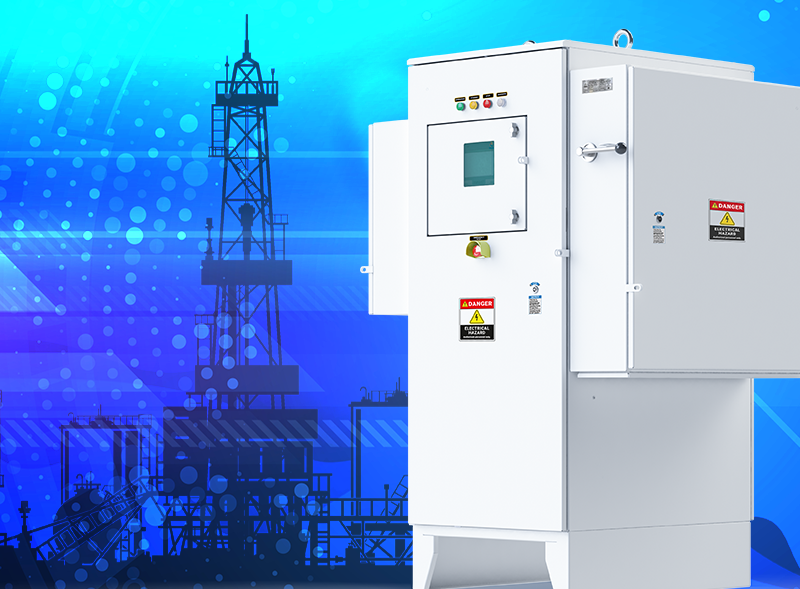
When working with ESP, the following requirements are imposed on the control and recording equipment:
- stable work with IM and PMM motors
- versatility of equipment for working with IM and PMM
- minimum commissioning time of the installation
- maintaining the operation of the installation in emergency situations
- 100% guarantee of working off protection in emergency situations
- minimum dimensions with maximum performance
- high efficiency
- reliability
The challenges we set ourselves to satisfy each of our customers and users and our solutions:
Mechanical protection of personnel from electric shock, including mechanical blocking of the doors of power cabinets when voltage is applied to the VSD, as well as the automatic shutdown of the VSD in case of purposeful unauthorized access to the power cabinets during VSD operation.
Multifunctional controller of new generation UMKA07 with a friendly and intuitive interface, LCD-TFT 7 inch display, touch screen, built-in non-volatile memory. UMKA07 allows you to set up the operation of the equipment in the shortest possible time, as well as update the firmware of the drive and controller using the software loaded from the flash drive

- An intelligent assistant Wizard for step-by-step adjustment of the vector control mode of the permanent magnet synchronous motor (PMSM), based on the algorithms for determining the moment of inertia, Lsd, Lsq.

- Triol Surface Card with a 3.5-inch display, which allows receiving telemetry from the submersible unit and transmitting the following data to the UMKA07 controller, SCADA or to the user's smartphone connected via Wi-Fi:
- Motor oil temperature / motor winding temperature;
- Temperature at the motor intake;
- Vibration in 3 planes;
- Pressure at the pump intake;
- Pressure at the pump outlet;
- Insulation resistance / leakage current.
The presence of these parameters allows you to protect equipment and increase the turnaround time, even in wells with complicated conditions.
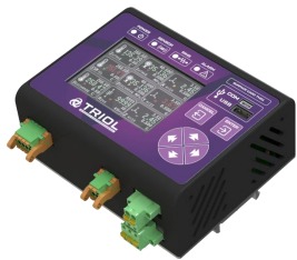
The arrangement of the power and control electronics contributes to an increase in maintainability and allows you to replace the electronics unit, part, assembly in the field without the use of soldering.
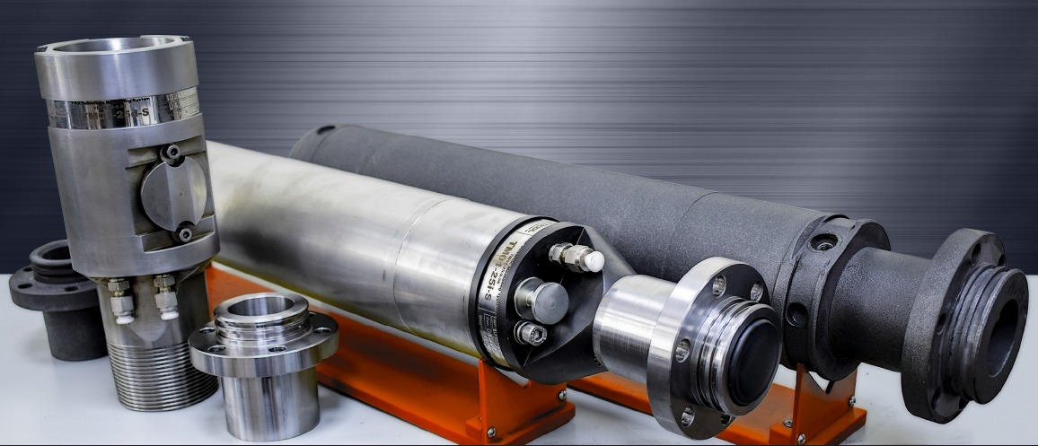
Work with different motor manufacturers due to the versatility of VSD to work with IM and PMM, and TM01, which provides the connection with different motor manufacturers and work with sensors of type RDT or J.
Vector control of the permanent magnet synchronous motor (PMSM) allows the increase of efficiency by controlling the motor taking into account the current position of the rotor of the motor and achieving a high cosφ of the motor with a decrease in energy consumption. The rotor position is determined by constructing a mathematical model of the PMSM according to the measured parameters based on the algorithm for auto-detecting the motor parameters.
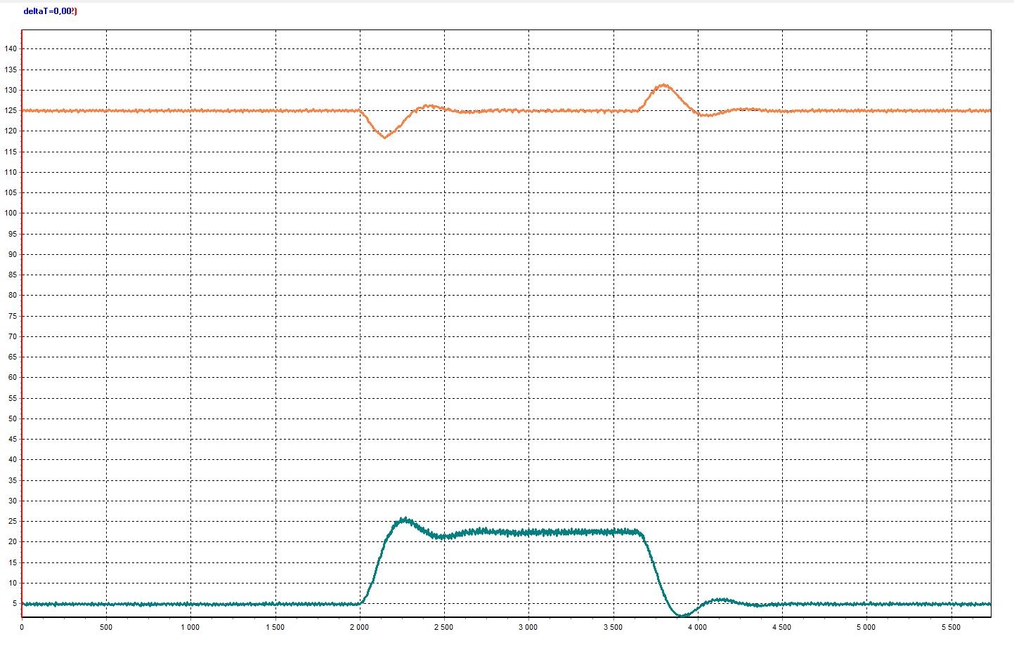
Orange - motor speed, rpm
Blue - Moment, Nm
Suppression of higher current harmonics allows minimizing the effect of harmonics generated by the VSD on the electrical main, saving electricity, reducing the risk of overheating of the transformer or supply generator windings through the use of multi-pulse systems 12, 18, 24 or a built-in passive filter

Harmonic spectrum of control system with the passive filter at the input
The efficiency of the solution is confirmed by the IEEE 519-2014 certificate of conformity.
Ensuring the protection of the motor, pump and VSD by monitoring the parameters of the installation using TM01 and the implementation of software protections in UMKA07. Monitoring the temperature at the pump outlet allows you to track the onset of bearing wear, which in turn allows predicting the replacement of equipment or adjusting the operation of submersible equipment to increase the overhaul period. Some of the protections have the ability to automatically increase the response time in the automatic reclosing (AR) mode in order to reduce shutdowns when alarms are often triggered.
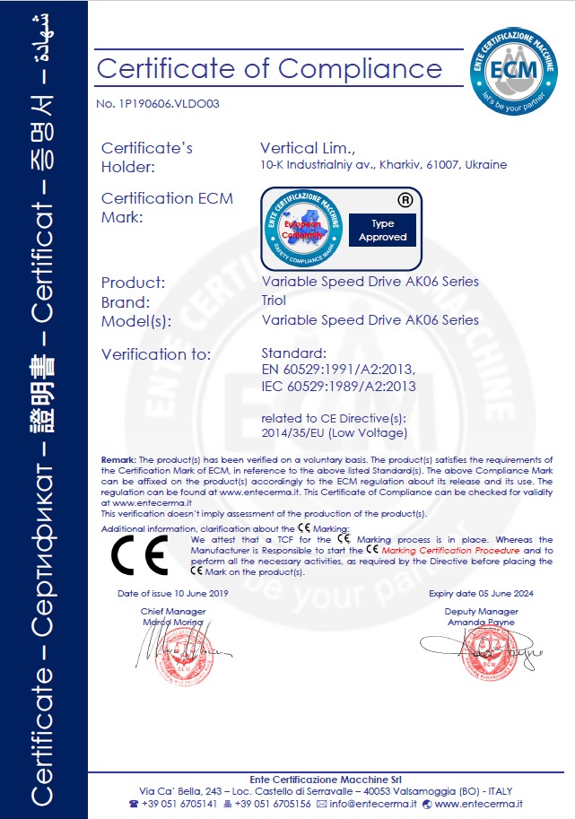
Degree of protection of the enclosure NEMA4 / IP66, ensures reliable operation of the equipment throughout the entire service life in a wide variety of operating conditions, including tropics and deserts.

The degree of protection of the equipment is confirmed by an international certificate:
Maximization of production due to the accuracy of measuring the pressure in the formation, which allows maintaining a low dynamic level and increasing the inflow from the well.

Flow rate versus pressure measurement error
The kinetic buffering algorithm allows for the work in mains with voltage dips up to 45% of the nominal within 200 ms.

Red – DC-voltage
Blue – Supply voltage
Green – VSD full current
Pink – VSD output frequency
Black – VSD output voltage
The algorithm for removing gas plugs allows, when the installation load decreases, the prevention of the "Underload" accident and brings the installation to the nominal mode. The algorithm consists of the fact that when detecting a drop in the motor load to the mode activation value, the output frequency changes at a given rate to a value set by the user and an operating time at a given frequency, followed by a transition to a second set frequency. The algorithm can repeat the alternation of frequencies for a specified number of times, after which the load is analyzed and, if the load is restored, the algorithm ends, if the load is not recovered, then the cycle is repeated several times. As a result, gas is pumped out of the pump and the supply is restored.

Red - Frequency, Hz
Green - Motor load,%
Wedging Algorithm, allows it to start a wedged pump in operation. Let's consider two main modes:
- Jogging, allows a constant frequency set by the user to raise the output voltage, the output current increases and the torque increases as a consequence. As a result, the motor starts to rotate. The user can set the number of repetitions and the voltage rise time.

Blue - VSD output voltage, V
Red - Frequency, Hz
- Swinging allows the installation to wedge due to the rotation of the motor in the forward and reverse directions with an increased output voltage of the control system. The user has access to setting the number of cycles, the amount of voltage rise and the speed in the forward/reverse directions.

The programmed mode of starting the installation, allows you to change the output frequency of the VSD with a low rate which makes it possible to smoothly increase the pump productivity when bringing the well to the nominal mode, while the underload protection of the installation works due to the variable setting.
Interaction with the periphery through the support of telemetry protocols: Zenith, Oxford, Borets, WellLift and others, as well as through analog and digital inputs/outputs.
All of these are the components of successful and reliable interaction between the Triol corporation and our partners in the oilfield service companies and oil companies who have practiced in different regions of the world.

These results are achieved due to:
- polypropylene capacitors in the DC link;
- polymer capacitors in control electronics;
- minimum number of detachable connections in signal and power circuits;
- optimization of elements in the control electronics;
- water resistance of control electronics blocks using varnishing;
- key components from trusted suppliers such as Semikron, Infineon, Electronicon, EBM-Papst;
- redundancy of cooling system fans (optional in the AT27 VFD);
- application of the power cells bypass using HOpCoD™ technology (optional in the AT27 VFD);
- liquid cooling (optional in the AT24 VFD).
In the AK06 VSD, smooth operation is ensured by:
- The kinetic buffering algorithm, which ensures operation with voltage sags up to 45% of the nominal value for 200 ms.

Red – DC voltage
Blue – Supply voltage
Green – VSD full current
Pink – VSD output frequency
Black – VSD output voltage
- An enlarged DC link, which allows operation in mains with voltage sags up to 100% of the nominal value for 100 ms (optional). Red – VSD output current

Blue – Supply voltage
Black – DC-voltage
- An uninterruptible power supply, which is powered by the VSDs AK06 control system, and a gauge system to transmit information about the condition of the AK06 and submersible equipment during the loss (optional).
In the AT27 VFD, smooth operation is ensured by:
- Bypassing a failed power cell with a bypass unit using HOpCoD™ technology.
Bypassing a failed power cell allows the variable frequency drive to remain operational. At the same time, the bypass of the power cell is carried out in hot mode, less than 4 ms from the moment of the failure, without interrupting the operation of the mechanism and the technological process.

Bypassing power cells in the AT27
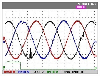
Time diagram of the output voltage at the moment when bypass of the power cell is operating.
- Ventilation reservation for air-forced cooling
An additional cooling fan is installed in the AT27 VFD for ventilation reservation. All fans, including the spare one, are in operation at the same time. Load is distributed evenly between the whole cooling system as there are more fans, they operate in light mode, which is beneficial to the resource. All fans are supplied with gravitation valves, which can maintain the operation of the whole cooling system if one of the fans has a fault. In the standard operational mode of the exhaust fans, a pressure difference is created on the freely rotating blades of the gravitational valve, which raises the blades and opens the channel section for heated air emitted from the AT27 drive to the outside. If one of the fans has a fault, a reverse pressure difference is created on the valve blades, caused by rarefaction inside the cabinet generated by the operating fans, and atmospheric pressure outside the cabinet. Under the influence of this pressure difference, as well as under the influence of gravity, the valve blades go down, blocking the cross-section of the air channel and preventing the "suction" of air outside the cabinet by other fans and a decrease in the efficiency of ventilation.

Operation of the Triol AT27 frequency drive gravity valve
- Software and hardware that allows a shockless start-up of a power multi-winding transformer, which avoids emergency shutdowns of co-operating equipment in conditions of limited power of the power system. The functional diagram of the system of pre-charging and soft start of the power transformer is given below :
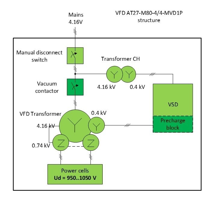
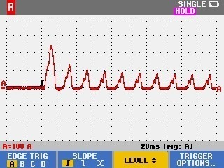
inrush current oscillogram of transformer without mains synchronization

inrush current oscillogram of transformer with mains synchronization
In both the AT24 and AT27 VFDs, smooth operation is ensured by a kinetic buffering algorithm, which ensures stable operation of Triol frequency drive operating with an induction motor in the case of deep and asymmetrical sags of the supply voltage, and even at its complete loss. Input voltage loss can occur as a result of emergency processes developing in the network, as well as during operation from a weak mains during shredding of hard-to-grind wastes. In this case, the quality of the output supply voltage remains within the declared parameters of the frequency drive, which does not affect the serviceability of the electric motor and the integrity of its insulation.

In the buffering mode, the variable frequency drive performance is maintained by consuming part of the kinetic energy of the rotating mechanism and then instantly restoring the set operating mode of the mechanism when the power supply is restored.
The VFD operating time in this mode can range from 5 periods of mains voltage to tens of minutes.
High efficiency is provided by the following solutions:
a) The vector mode of the permanent magnet synchronous motor (PSM) allows increased efficiency by controlling the motor, taking into account the current position of the motor rotor, and achieving high cosφ of the motor with reduced power consumption. The rotor position is determined by building a mathematical model of the PSM according to the measured parameters based on an algorithm of automatic determination of motor parameters.
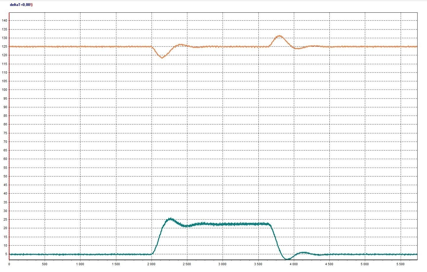
Orange – Motor speed, rpm
Blue – Moment, Nm
b) Vector control of the induction motor with motor torque limitation algorithms and motor speed control in the Triol AT24 variable frequency drive provide reliable motor overload protection, while maintaining high speed accuracy over the whole adjustment range.

c) Production is maximized by measuring reservoir pressure accuracy to maintain a low dynamic level and increase flow from the well.
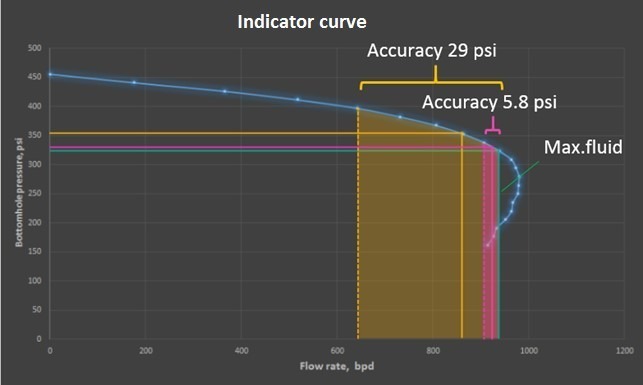
Flow rate dependence on pressure measurement inaccuracy graph
d) The gas plug removal algorithm prevents under-load failure and brings the equipment into nominal mode when it is under-loaded. The way the algorithm works is that, upon detection of the motor load drop to the mode activation value, the output frequency is changed with the preset ramp up to the value set by the user and the operating time at this frequency, followed by the transition to the second preset frequency. The algorithm can repeat alternating frequencies a specified number of times, after which the load is analyzed and, if the load is restored, the algorithm is terminated; if the load is not restored, the cycle repeats several times. As a result, gas is pumped from the pump and the flow is restored.

Red - Frequency, Hz
Green - Motor load, %
e) The wedging algorithm allows you to start the jammed pump in operation. Consider two basic modes
- Jogging mode raises the output voltage at a constant frequency set by the user, which increases the output current and torque. As a result, the motor starts to rotate. The user can set the number of repetitions and voltage rise time.

Blue - Output voltage of VSD, V
Red - Frequency, Hz
- Swinging mode unclips the unit by rotating the motor in forward and reverse direction with increased VSD output voltage. The user can set the number of cycles, the voltage rise rate, and rotation speed in forward/reverse direction.

Blue - Output voltage of VSD, V
Red - Frequency, Hz
f) The program start mode of the unit allows you to change the output frequency of the SU at a low rate, which allows you to smoothly increase the efficiency of the pump when you bring the well to nominal mode, while providing protection against underloading the unit, due to the variable setting.
g) Direct connection of the AT27 medium voltage VFD to the mains and to the motor without additional step-down and step-up transformers. AT27 has a high efficiency not less than 97%, which is much higher than similar solutions using low-voltage frequency drives, working on a double-transformer scheme, where the efficiency is 92% on average.
The high efficiency is achieved by:
- High efficiency of the power transformer ≥ 98.5%;
- High efficiency of the voltage inverter ≥ 98.5%;
- Optimized power consumption of the air-cooling system fans depending on the load.
AK06 VSD and AT24/AT27 VFDs have extended capabilities of communication with external devices through digital communication ports implemented by RS-485 and Ethernet interfaces with MODBUS RTU, MODBUS TCP/IP exchange protocols. PROFIBUS, PROFINET, and others are optionally available.
AK06 and AT24/AT27 can be integrated both into existing well pad automated control systems and into remote parameter monitoring systems via satellite or mobile communication channels, via existing communication channels, and by installation of additional modems.
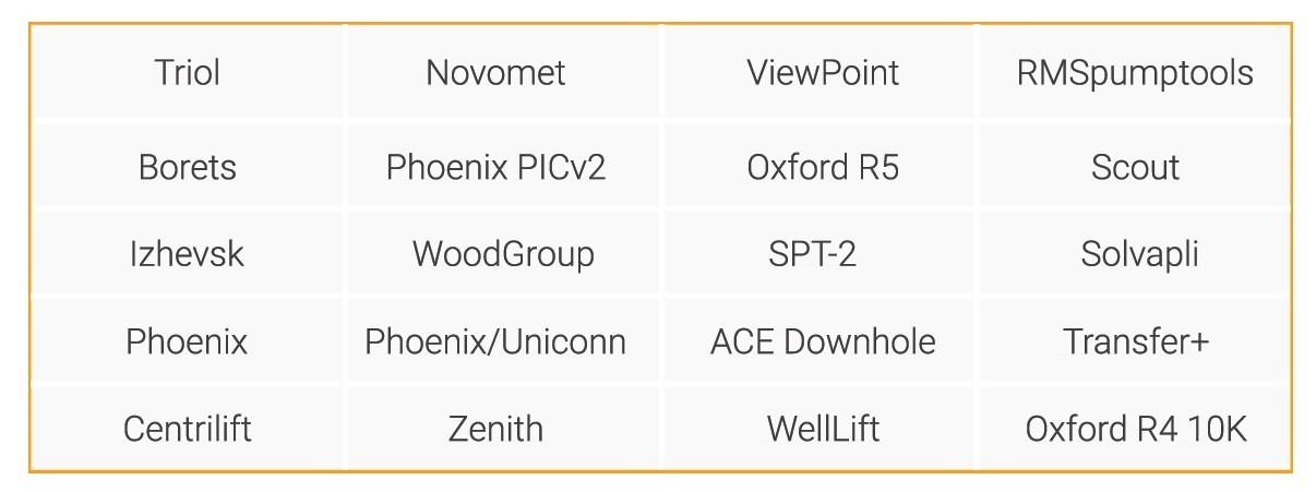
There is extensive support for gauge systems from various manufacturers:
For offshore platform environments where equipment is located indoors, we offer AK06 in the following lines:
RD Line
LH Line

For indoor offshore applications we offer the AT24 cabinet VFD with IP21/IP55 rating, with built-in or plug-in sine-wave filter, and air and liquid cooling.

Installation of Triol equipment on platforms in tight spaces becomes the optimal solution due to small dimensions and one-way service.
The liquid-cooled MP series application makes it possible to install the variable frequency drive in rooms without air ventilation.
For operation in offshore platforms when the equipment is located indoors, we offer the AT27 cabinet VFD with IP42 degree of protection with built-in sine-wave filter, ground gauge unit and chock, as well as the voltage drop compensation algorithm in the cable line.
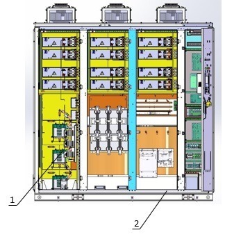
- Sine-wave filter compartment
- Compartment of the ground telemetry unit and chock.
Triol Corporation's solutions allow
- Maintenance of the VFD in the indoor climate of offshore platforms.
- Operation with a long cable line of up to six thousand meters (AT24, AT27).
- Compilation and use of information from the submersible unit in your work.
For operation on an offshore platform when the equipment is placed directly on the platform, we offer AK06 in the following lines:
UD Line

CP Line

PS Line

For offshore applications on platforms, we offer AT24 cabinet VFD in a NEMA 4X enclosure, with built-in sine-wave filter and air cooling, as well as a liquid-cooling VFD with IP66 enclosure.

For indoor offshore applications we offer the AT27 MV line drive in a NEMA 4X enclosure, with built-in sine-wave filter, and a ground-based telemetry unit and chokers.

A specific feature of the proposed solutions is:
- space saving
- dual-circuit air cooling system
- liquid cooling (AT24 VFD)
- stainless steel enclosure
- built-in sine-wave filter providing an output THD ≤ 5%
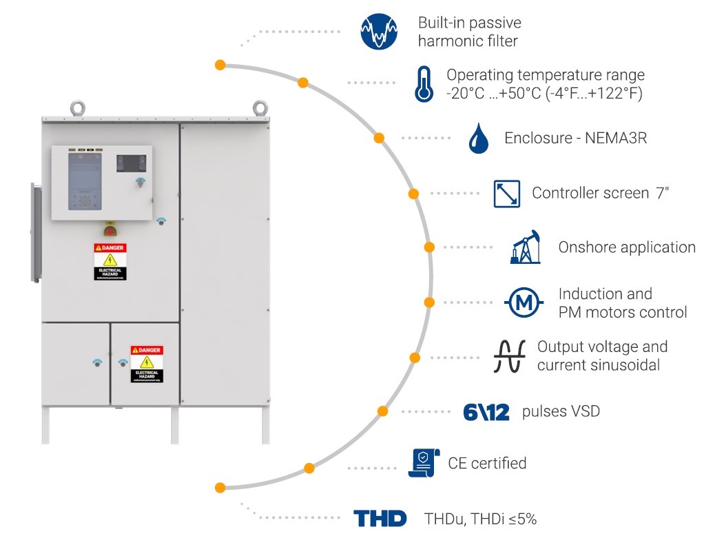
- low input THDi by using a 12, 18, 24 multi-pulse circuit (AK06 UD line), built-in passive filter (AK06 SR line), or built-in multi-pulse autotransformer (AK06 PS line).
AK06 VFDs are equipped with the following staff protection features:
а) External light indication of equipment status: "Operation", "Waiting", "Stop", and "Turbine rotation".
b) Mechanical protection of staff against electric shock, including mechanical locking of power compartment doors when voltage is applied, as well as automatic shutdown in case of deliberate unauthorized access to the power compartments during operation.
c) Electromagnetic locking of power compartment doors, preventing the doors from opening while there is voltage (optional).
d) Protective polycarbonate screens to protect staff from accidental contact with current-carrying parts.
e) Protective grounding of metal parts of the enclosure.
AT24 VSDs are equipped with the following staff protection features:
а) External light indication of equipment status: "Operation", "Ready", or "Failure".
b) Protective polycarbonate screens to protect staff from accidental contact with current-carrying parts.
c) A mains-wide leakage current protection that continuously measures the active insulation resistance and disconnects the mains if the resistance falls below the specified values.
AT27 VSDs are equipped with the following staff protection features:
а) Indication of voltage presence in AT27 power cells.
b) High voltage indication in the switching compartment for AT27 DD and MV lines.
c) Indication of voltage presence in the DC link of power cells on the screen of the UMKA-27 controller and LED indicator on each power cell.
d) External light indication of equipment status: "Operation", "Ready", and "Failure".
e) Disconnector and grounding switch on the power supply input in the switching compartment of the AT27 DD and MV lines, and CB27 switching cabinets for the AT27 ED line.
f) Electromagnetic locking of power cabinets and compartments doors, preventing the doors from opening while there is voltage (optional).
g) Optical communication channels of the control system with power cells and transformer temperature measuring units.
h) Smoke detectors for fire alarm (optional).
We offer the following solutions for installation on offshore platforms:
а) AK06 FC line is a compact solution in a NEMA 4X enclosure with operating temperature from -20°С (-4°F) to +40°С (+104°F) made of stainless steel. It has the option to integrate the AT24 UC line as well as third-party manufacturers, which reduces staff retraining costs for equipment operation, and also increases the protection rating of the VFD in the application and expands its capabilities with a built-in sine-wave filter, which provides THD ≤ 5%.
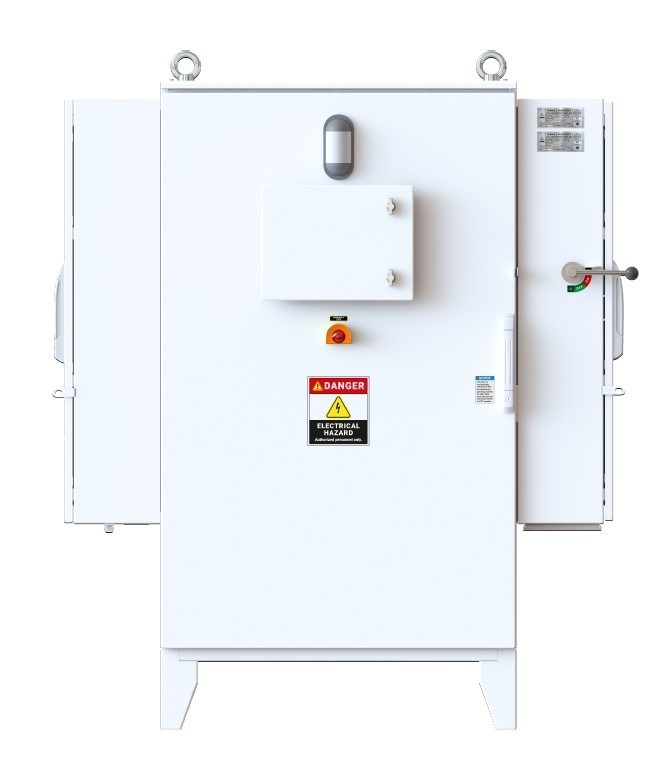
b) The Triol E-Cabinet is a compact, complete product in a NEMA 4X enclosure with optional protective coating, with an operating temperature range of +20°C (+68°F) to +40°C (+104°F). It is made of stainless steel and consists of a dry 12-pulse step-down transformer (SDT) with a nominal voltage of 4 kV, a variable frequency drive (VSD) with a nominal voltage of 480 V and dry output step-up transformer (SUT) with adjustable taps from 1.5 kV to 5 kV.
The equipment is supplied with a system for measuring and controlling transformer winding temperatures, a fire alarm system, and a dual-circuit cooling system.
The service is single-sided, resulting in size savings when installed on the offshore platform site.

c) The AT27 is a special version for oil production and has the following advantages:
- NEMA3 outdoor rating – no need to install in a room with additional air conditioning
- More compact than a control station + step-up transformer system
- Complete product (VSD, passive filter and sine-wave filter in a single enclosure)
- Rated voltages of 1.3–2.6 kV
- Motor control directly instead of over step-up transformer
- High efficiency ≥ 97%
- Low THD of input current and voltage – complies with IEEE 519 (<5% THDi, THDu)
- Low THD output current and voltage (~3%)
No transformer on the output: minimum weight and dimensions, effective operation at low frequencies, increased efficiency of the variable frequency drive, reduced maintenance costs, environmental friendliness.
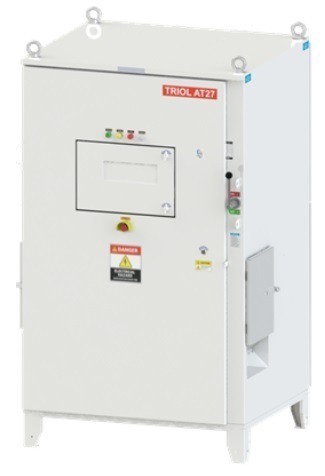
Triol Corporation offers AT24 and AT27 variable frequency drives in ATEX certified cabinets for indoor installation in hazardous areas. All cabinets are made of stainless steel. The use of these cabinets in hazardous environments is classified as "ATEX II2" or "II3", which ensures complete safety of the equipment in conditions where explosive atmospheres may occur.
The suppression of higher current harmonics minimizes the influence of the harmonics generated by the frequency drive on the electrical mains, saving electricity, and reducing the risk of overheating the windings of the transformer or supplying generator by:
- Applications of 12, 18, 24 multi-pulse rectifier systems, built-in passive filter, or 12, 18, 24 multi-pulse systems with built-in autotransformer in AK06;
- Active rectifier applications in the AT24;
Applying multi-pulse rectification schemes 18, 24, 30 without installing additional input filters and reactive power compensators in the AT27.
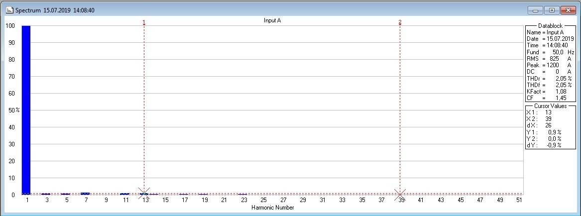
Input current harmonic spectrum (THDi ≤ 5%)
 1(405)6157755 (Business)


 Google
